In the simple analysis of the bolted joint it has been usually stated from the connection with one bolt, which is loaded by a force that is introduced somewhere within the bolt axis. Although this is a very useful simplification because it results in a linear behavior and leads to a relatively simpler calculation, the actual axial loads act very rarely or not at all, in this way.
In addition, the connection with only one screw is rare. As is known, the multi-screw connections are the basic form of the connection. By non-linear behavior, which is dependent on many factors and usually results in the massive increase in stresses in the connection, the conditions in this form of connection are very complex. Numerous theoretical and experimental investigations in Germany and France confirm this. Nevertheless, the behavior of multi-bolt connections is by previous methods not so well represented such as the behavior of the single-screw connections, as to provide an effective basis for the designer. Unfavourable is because the models such as the VDI model for example give a linear variation of the additional stresses (tensile and bending moment) depending on the external load and then tend to overestimate it for low loads, while in the higher load they overlook how dangerous they are.
Because of this, construction of a highly loaded bolted connection come very often to the limits, especially when an "over sizing" due to economic, weight limits and other reasons, is not a viable option.
The basis of the procedure concerning the determination of the so-called force introduction factor (n) is disputable. In the case of the centric assembly preload of the connection, all forces, behind the screw preload force FV and the reaction force in the separation surface FK, act along the bolt axis (see Fig., a). The clamped parts are pressed together, where the counting compliance is . Under the eccentric external load, this effect separates (see picture Fig. b), so that for the preload (mounting) determining compliance is divided into the effect of the bolt force and the effect of the force in the separation surface:
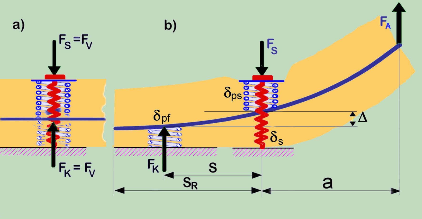
Clear that this effect manifests itself differently and therefore does not have anything to do with the position of the force introduction of the external force along the connection axis. Based on the VDI prove, the designer may in the case of greater eccentricity come to the conclusion that he may neglect the effect of force introduction, although a very strong effect exists, but due to the very different coherency.
Related relationships are analytically determined in the framework of a new beam model of the connections:
Structural Integrity Analysis of Multi-Bolted Connection Using the Innovative Beam Model, in STRUCTURAL INTEGRITY AND LIFE, Vol. No. 3 (2011), pp. 147-156)and the corresponding calculation examples (free downloads for the both!)
The suitability and necessity of using this method of analyzing a particular connection is dependent on the stiffness ratios of the bodies that are connected (beam, plate, etc.).
From the formula for determining the clamping force in the connection (above cited sources)
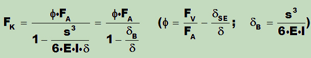
It can be seen that only if δB << δ, one may neglect the effects of bending deformation in the connection and the application of classical linear models may make sense. Higher bending compliance, on the other hand, causes the significant increase in clamping force in the connection and a substantial increase in all forces in the connection.
Because the change in clamping force eccentricity (s) is generally limited in one connection (edge distance), this also limits the maximum increase. However, the increase in the forces after that is even faster according to the levering and gaping of the connection.
Since the modern designs are dominated by lightweight construction, the application of the proposed beam model is in most cases necessary.
Considering bending deformations in the joint caused by typical eccentric introduction of the external load is a turning point in the consideration of bolt connection. Thereby, Rotscher's cones, position of force application, etc. alone are not decisive factors for the behavior of a screw connection (except for the consideration of the preload of the connection). Also the gaping (lifting) of the connection changes seriously.
The determination of the eccentricity "a" involves a great deal of risk, because the screw connection can not be considered separately from the rest of the structure (plate, flange, etc.). As already mentioned,, at the place of the connection clamping to the remaining structure in addition to the force, there is also the moment MB, that must be considered and the stiffness ratios in the connection are not independent of the remaining structure. The determination in this respect, which is not at all easy, in the many calculation models has been left to the user, by which of course the potential pitfalls are exceptionally large. By less accurate determination of the relevant parameter of the load, the results of the calculation will be called into question.
It is a fallacy, one can elude these all problems elegantly, by resorting to the FE method. On the contrary, already in modelling for FE analysis, one realizes how complex a bolt connection is. The results of the finite element analysis will be definitely influenced by the kind of the modelling of the connecting parts, application of the preload in the connection, consideration of the contact conditions in the separation surfaces, by the changes in load distribution and, not least, by the type of the consideration of the non-linear behavior.
In order to assist you in the design of the FE models, without putting into question the accuracy of the results by the required effort, relevant points of concern are handled here in detail.
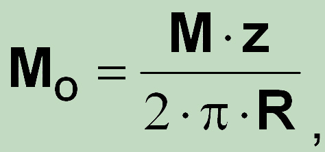
The effect of the coefficient bi, which in the above model represents the conditions for the pairing of the connection segment into the main structure, is much more effective. The physical meaning and the evaluation of these influence numbers can be demonstrated by the example of the bolted plate (or cover). For the circular plate of constant thickness due to Roark's Formulas for Stress and Strain (by WC Young and EC Budynas, Seventh Edition) from Table 11.2, Case 13 (page 490) follows (after substitution of symbols θo = α and a = R)
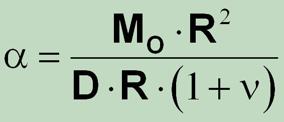
After getting into account the number of bolts, it follows for bending moment along the bolt segment
so that the above relationship can be given in more general form
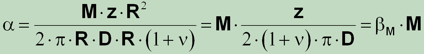
with
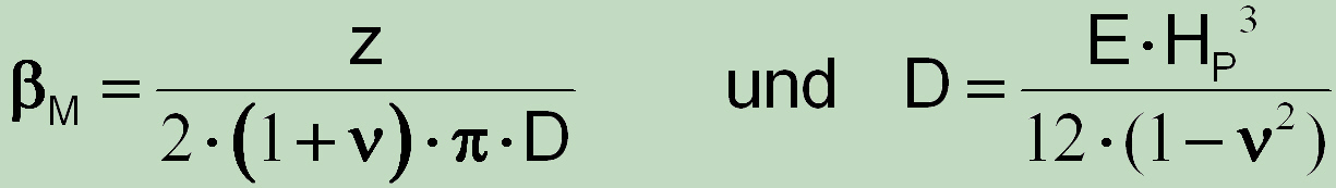
For the evaluation of
we also need
![]()
After the substitution this leads to the result
which shows that this influence number is based on the diameter at coupling corrected by the ratio of thicknesses of the base circular plate and the bolt segment.
Or simple by writing ![]()
Analytical studies have clearly shown that the stress conditions in a joint are determined not only by a ratio of stiffness, but also rather by the relationship between preload and working forces. Accordingly, the height of the preload force is very important parameter for the integrity of the structures with bolt connections.
The high sensitivity of bolts against fatigue loading, due to the large stress concentration resulting from the threads, causes that the bolts which must endure cyclic loading, are tightened high up to very high preload, to dam up the fatigue loading of the bolts in the connection, what is, however, only taken into account by the non-linear calculation.
In practice, through the tightening above yields, this fact has been accounted for a long time. Lastly, virtually at the dynamically loaded connections in the engine, even if in that way the level of mean stress rises sharply. Obviously, the reduction of the stress amplitude is more crucial in this case.
Even though it should be considered, that in the service, after rejection of the external loads, the bolt preload reduces to the original level along the original curve (linear elastic line), only if the maximum bolt stress was below the yield level. The behaviour of the system stays purely elastic (regardless of the non-linear behaviour!!) only if the total load remains in the elastic region. Plastic deformation of the bolt and the clamped parts through an overloading will always result in the loss of preload in the connection. This means after exposure above elastic limit, as a consequence, all subsequent loads will cause higher load partitioning to the bolts in the connection.
Additionally, for some materials that are extremely sensitive to the mean stress level, nevertheless, this overall context must be studied more carefully.
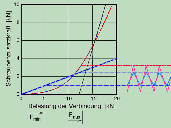
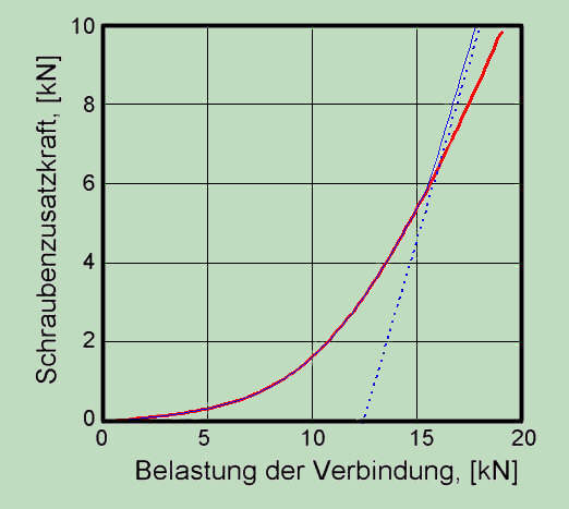
Consideration of the non-linear behavior is particularly significant for the dynamically stressed connections. This can be shown by the model of previous computations. If the external dynamic operating load varies between 5 and 12.5 kN this yields for two calculation - linear and nonlinear � to the significant differences in stress amplitude. The increase of the stress range can arise both in the direction of the minimum voltage and in the direction of maximum stress, which in summary results to the considerable differences in the fatigue stresses of the bolt. Because of this, this cannot be avoided even with a more conservative linear calculation (larger slope of the blue line in diagram).
For complex structures, is further usual the values that are exposed to random influences (scatter) to treat statistically. And that is with regard to the elevation of the tightening force important. In particular, attention to be taken to the fact that the multi bolted connections are very often dominated by Fail-safe behaviour, where the failure of one bolt can be carried out through the carrying capacity of neighbourhood bolts (at least for a limited time). This means, for the consideration of the dispersion of the preload force, it is necessary to include in the consideration the number of bolts and the kind of the loading conditions. The difference in this respect, for example, between the static pipe flange and the shaft flange, which is loaded circumferentially is obvious.
As a result, the so called tightening factor for the multi bolted connection can not be the same as for the connection with one bolt.
As well known, a part of the setting is compensated at montage by rising tightening force. Through eccentric outer loads the clamping-force transfers itself with increased load from the position of the connection-axis. With it the new contact areas were enclosed that also leads to the additional embedding, which is no more compensated (during assembly) and consequently leads to the effective reduction of the preloading force in the connection that must be taken into account additionally.
Concerning the multi-bolted joints is the so-called "lever principle" in its primitive form, a coarse simplification, which is also on the unsafe side, and therefore really should not be recommended. The procedures which are based on this assumption ("circle arc") are just as vague and on the unsafe side. The relations developed for the more exact beam model and test results show that this transition always takes the form of the parabola.
Individual connections, in which the so-called deformation cone has been cut on all sides, present the typical case of the connections with the limited external dimensions. Such slender cylindrical compounds behave strongly non-linear. For the treatment of such compounds, the non-linear method has been developed by author [Konstruktion 27(1976) S. 192-97)], which is taken out, unfortunately, from the latest edition of VDI 2230.
Non-linear modell for calculation of joints with one cylindrical boltThere are little doubts that the bolted joints are one of the major sources of nonlinearity in mechanical structures. This produces considerable additional stress not only for the bolts but also for all the parts in the joint.
Although linear models are seen usually to be conservative - this is in the case of multi bolted connection rare the case! Application of linear models with smaller loads leads to over conservative results. In opposite, if the higher loads are expected, their effect will be underestimated. In both cases, the reasonable lean design will fail.
Linear models are wrong. It is senseless to study the behavior and the parameter variations and uncertainties with an incorrect model form.
Perhaps the most significant shortcoming of the known models is that the function of this connection is reduced to only two control parameters: compliance of the parts in the direction of the screw axis and the guarantee of the sufficient preloading minimal force. All other factors such as the bending stiffness of the connected parts (plates, cylinders, etc.), the actual position (eccentricity) of the external force, the magnitude of the preload force and the preload bending moment, the onset of the increased stresses because the connection is no longer intact (Prying), etc. remained virtually ignored.
In contrast, the safe and conservative methods, based on the beam model are available for the design of screw connections. From the author, due to the consideration of the fundamental relationships of strength theory, the previously proposed beam model has been further developed over its origins, based on practical experience and studies of other authors. Using this advanced model, the bolted connection can be modelled in a more accurate manner by considering non-linear behavior and conditions for adequate function.
You want to know more about it? Clear! Please have a look at the detailed documents about